Current Flow in an (AC) RC Circuit (Low Pass Filter)

Hi!

Ever since Veritasium’s video on current flow I have been re-examining and questioning everything i “know”. I was looking into Low Pass filters - I have always applied the formulas for the 3dB cutoff point I need, maybe used a simulator, got the result and called it a day! I am comfortable with the math if need be or to use a phasor diagram. However, I was thinking about the current flow and I fear I am missing a fundamental concept

let’s take this circuit

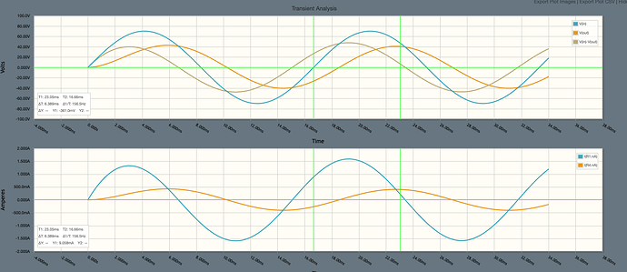
and running it through the simulator, we can see this

From t=0

  • Vin increases in the positive direction, as such current starts to flow, and the voltage across the capacitor increases as charge builds on the plates.
  • as long as Vin > Vc (Vc = Vout), the voltage on the capacitor will continue to rise, albeit after the peak of Vin this will slow
  • the current through the resistor is essentially in line with Vin
  • When Vin = Vc, (around t=6ms), the capacitor will begin to discharge. This will mean the current will reverse - and indeed, at 6ms Ir goes negative - this implies that despite Vin still being positive and pushing current into the circuit, it is being opposed by the voltage on the capacitor, as the voltage on the capacitor is higher it is forcing current back into the voltage source

my question here is, what is the real world implications of this? I have been thinking about various voltage sources, like an AC generator, and how that would handle current coming back in when it’s still generating a positive voltage and trying to drive current. This lead me to think about smoothing capacitors in rectifiers - however in this case, there are diodes that prevent reverse currents and so the smoothing capacitor will discharge into the load - RC filters don’t appear to do this.

I pulled out my Art of Electronics to see what they had to say on the topic, but didn’t find much on the implications of the current flow. I can follow the math and can draw the waveforms I see - however thinking about the actual current flow here has got me stumped i must admit!

I have seen examples where the RC filter is driving an op-amp; an op-amp having an extremely high (ideally infinite) input impedance, won’t accept current in, and so in this case again, the discharge current from the capacitor in the filter must go back toward the source.

When the capacitor discharges, for a period in time whilst Vin is still positive, we have two voltage sources in parallel with different voltages which is generally not considered a good idea. The resistor in between will create a voltage drop of IR - if we look at the point 7.8ms, the current through R1 is -1A, with a 30 ohm resistor we would expect to see -30v across R1 and indeed Vin - Vout is - 30v. However the current must still flow somewhere and as far as I can see it can only go back into the source

I had thought that as there was no load, it doesn’t really make sense - sure you can construct the circuit without a load (and again, the only place the discharge current can flow is back to the source; this would also be the same case as connecting an op-amp with high input impedance), but to be sure I can add a load; the voltage across is still Vout = Vc, but we can see a current through that follows Vc/Rload - which makes sense at face value, but again, not if I think about where the currents are flowing!
image

As the capacitor is discharging, we know there must be a current flowing! but where does it flow to? without a load, it can only go one way; with a load there is a discharge path, but then i’d expect the current through R1 to change accordingly…

I have been thinking back and forth on this for some time! I am really, really sure I have missed a fundamental concept here - I can follow the math to get the answer, but conceptually it seems to be messing with me!

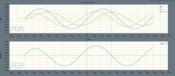
I have been thinking about this and this is what I came up with; i’d appreciate any feedback on my analysis

  • as is always the case with voltage, it’s the difference in potential between two points that matters; if there is a potential difference, there will be an electric field and thus current (opposite the direction of electric field of course).

  • an electron doesn’t care what else is around, all it knows is “there is an electric field, i’d better move!”, and since Vcap > Vin, there will be a potential difference and the source just has to suck it up and deal with it!

  • if we remove the load from the circuit (for example we could be feeding an (ideal) op-amp), then there is only one way for the current to go, back through R1 an into the source. Anything else is impossible

  1. let’s consider an AC power source from a coil rotating in a magnetic field with slip rings
  • the rotating ring generates an EMF proportional to the number of turns, the magnetic field strength and the speed of rotation.

  • the generated EMF will exist across the coil, when connected to a load a current will be produced which is proportional to the circuit impedance as a function of time. The current that flows is only due to the fact that there is a potential difference across the coils and thus a field is generated in the wire that causes current to flow.

  • when Vcap > Vin, that current reverses due to the reversed potential difference, the fact that Vin is positive is actually irrelevant. the relative voltage is lower than Vcap… the fact that Vin is positive just means the relative potential difference is smaller.

  • being a simple coil of wire, the reversed current will just cause electrons to flow from the capacitor through the resistor, through the coil and into other side of the capacitor resulting in, over a few time constants, the capacitor returning to electrically neutral on both plates. this would be consistent with KCL

  • if we add a load, then we have have two loops for the capacitor to discharge through, back through R1 as above but also through the load. The discharge current will flow proportionally to the impedance of each loop. But I(R1) + I(R4) = I(cap) during the discharge part of the cycle. And the result is the same. And indeed if I look at the absolute value of the currents, I(cap) = I(R1) + I(R4)

  1. I looked at when the input is a square wave, i.e.: this circuit
    Click image for larger version Name:  fedevel_forum_1.png Views:  0 Size:  36.4 KB ID:  19835|attachment
    for this we get waveforms as below (the current being I(R5) - and we clearly see the negative current spike when the 555 switches off; again, this has no where to go but back through the output pin

Click image for larger version Name:  fedevel_forum_2.png Views:  0 Size:  41.9 KB ID:  19836|attachment
looking at the circuit internals for a 555,

Click image for larger version Name:  fedevel_forum_3.png Views:  0 Size:  64.2 KB ID:  19837|attachment

we can see that when the output is 0v, any reverse current will be passed through to circuit ground harmlessly.

assuming I am right in my analysis (which I think I am! and feel free to correct me if i’m not) - my intuition was right all along. And you do need to consider what you are connecting capacitors to, they will generate negative currents and you have to deal with that. And in fact, this is exactly the same with inductors - we are used to putting flyback diodes in to snub the reverse voltage generated with the electric field collapses!

Your intuition is correct, though because of R1 (30 ohms) in your filter there never is a time during which two voltage sources are truly in parallel.

When the capacitor discharges, for a period in time whilst Vin is still positive, we have two voltage sources in parallel with different voltages which is generally not considered a good idea. The resistor in between will create a voltage drop of IR - if we look at the point 7.8ms, the current through R1 is -1A, with a 30 ohm resistor we would expect to see -30v across R1 and indeed Vin - Vout is - 30v. However the current must still flow somewhere and as far as I can see it can only go back into the source.

Indeed, connecting two voltage sources in parallel is generally not a good idea unless they have virtually identical characteristics, because any imbalance in voltage will create a current that generates heat in the conductors and in the internal battery resistances. These internal resistances are distributed and, in many cases, rather complex to model.

Hi @Jverive - first up, thanks for getting back to me! and sorry for taking so long in replying: I seem to be in a funny part of life where you get periods of downtime where I can dedicate a lot of time to this, but it seems as soon as I post a question, life says “nope! deal with this instead!” - but today the kids are healthy and I’m actually getting some time to get back into this.

Before I continue, I will add in that, believe it or not, I have a degree in electrical engineering from many years ago, and after being out of the game for so long, things seemed to have disappeared from my mental cache; I spent time talking to my mum (a mathematics teacher) and we were discussing that when I was in college, my motivation was more not failing than true understanding… I got very used to just applying the formula, getting an answer and moving on. Which I pay the price for now, but am determined to correct. Hence I take as many courses as I can. This is part of a bigger project in building and documenting projects with my kids, and teaching them as we go - hence I am determined to give them the correct understanding, rather than some of the misunderstandings and misconceptions I have had. Thus there will be some more posts in this realm. This is why I am comfortable with the math, but missing some concepts!

with all that said - could you expand on this point:

“because of R1 (30 ohms) in your filter there never is a time during which two voltage sources are truly in parallel.”

if we had a 1.5v and a 1.3v battery in parallel, both will try and force the node to be their voltage, the connection between the two will be, in effect a very low resistance, and current will flow from the higher potential to the lower, meaning an extremely high current will flow from the 1.5v → 1.3v battery, dropping 0.2v across, essentially, 0 ohms. I assume along the wire then, there will be a voltage gradient, so the actual voltage on the node would depend on where along the wire you connected, and it would be somewhere between 1.3 and 1.5v. In reality though, the 1.5v battery would never be able to source that much current, and pushing that much current into the 1.3v battery would result in bad things happening! so… what voltage would be at the node would be a moot point!

now, as there is the 30ohm resistor there, they are, as you say, not truly in parallel - taking the same example above if we have a 30ohm resistor between a 1.5v and 1.3v battery, there would be 0.2v across that resistor and so a current of 6.7mA would flow from the 1.5v → 1.3v battery - and then it would be a question of the construction of the 1.3v battery how it would handle this.

However, I am unsure of how to apply this to the filter above, am I correct that yes! current will flow in reverse towards the voltage source, and you best be aware of that and deal with it appropriately?! for example, the 555 timer internally appears to handle reverse currents, and I assume most chips will as well - from the LM555 timer datasheet

image

“the output circuit can source or sink up to 200mA” - in my simulation above the max negative current is around -5mA, so well within spec

to one of my original points, this is something that I have never really worried about, and (so far!) have gotten away with, but in reality - in practical engineering of products, how do you deal with this? as I mention, I have done a lot of reading, but this doesn’t get much discussion, filters are handled from the impedance/reactance perspective as to their cut-off frequency and that’s it. Inductors get discussions of reverse-emf and flyback/freewheeling diodes, but I am yet to see reverse currents discussed as a result of capacitors and filters (or I’m looking in the wrong places!)

You just add 50ohms as equivalent series resistance in any formula. If your resistances are 20x 50R, you just ignore it, since the 555 is not a precision device anyhow

cheers @kvk - i assume you are referring, in this instance, to a 555 circuit? does this advice generalise to any circuit with an RC filter (sorry for the poor wording of my question)? for example, I have seen an LDO (making 3v3 for analog circuitry) and a buck converter (producing 3v3 for digital circuitry, powered from a USB port - the RC filter being on the input to the LDO.

doing my best DaveCAD…!

Regarding current flowing back to the source during those portions of the AC cycle in which capacitor voltage exceeds the source voltage, one or more of the following will happen: the source absorbs the energy, the load absorbs the energy, or the capacitor charges up a little bit more with each cycle. Most filters are designed with the first two of the scenarios in mind because the third is a rare occurrence, but it can happen in some circuit combinations. A well-designed audio source will be able to sink as well as source current, something that most good audio circuit designers learn somewhere along the way.

For power filtering the same rules apply, but unless the voltage drop across the series resistance is acceptable we usually replace series resistors with inductors (including ferrite beads). If the inductor is chosen correctly, it will be at least as effective as a resistor in the frequency band that contains the noise we want to dampen, since the inductor’s impedance is proportional to frequency (neglecting parasitic capacitance).

1 Like

@Jverive great answer, thanks!

“something that most good audio circuit designers learn somewhere along the way.” - i really like this statement as I think it summarises my situation perfectly; Although I have the theory, I lack the practical and real world experience. This is precisely what I am attempting to rectify with CE, and other projects. In the past I have relied on modules and pre-designed units hooked together. This achieves the end goal but avoids a lot of real-world issues, and things you gain by experience. Hence I am intentionally going slower, thinking about each step and understanding what I’m doing better, asking more questions. My goal now is understanding not necessarily the end product (the end product will be a bonus)

so, in summary, essentially I was correct, and one must actually be aware that a filter will generate some reverse current, and you better know where it will go.

You bring up ferrite beads - another topic I have on my list to investigate further, as far as I know these are for EMI? both preventing EMI radiating from the inductor and to capture any EMI that may come in from external source and preventing that creating noise on the traces?

A Bead simply has resistance at high frequency, so it dampens high Q circuits by turning the energy into heat

Beware that a Bead can have high inductance at lower frequencies so if not chosen carefully it can introduce more harm than good

All Beads are not created equal…

1 Like

Ferrite beads are generally most useful at high frequencies, and when used in a series path they simply become high impedance. At low currents (where they do not saturate) they return the captured energy to the source, though when they saturate some of the energy does get converted to heat.

These tiny inductors are even more effective at EMI suppression when they are combined with capacitors (usually in either π or T configurations), which you’ll find in numerous RF circuits.

Beads are resistive at high frequencies, dissipated the energy as heat and saturation is not involved in that function neither is returned energy

Ok, so we are basically just treating ferrite beads as inductors? (looking at the difference in opinion on where the energy goes, between @kvk and @Jverive)

here is a schematic I found
image

to the right is a buck voltage regulator to produce 5v - the input (either barrel jack or terminal block) is 12-24v. But here we see L5, L9 and L6 ferites - what role are they playing here? 100MHz seems to be high frequency filtering? is this from external coupling - or just in case the 12-24v power source has some high frequency ripple? or perhaps due to noise caused by the load switching? or some combination of all the above?!

this feels like those occasions where you draw on practical experience when designing a power supply?

No, they should be treated as frequency-dependent resistors and @kvk is correct. The energy is dissipated via a combination of hysteresis losses and eddy currents (tiny ones) in the ferrite bead. These occur regardless of any DC bias. If ferrite beads were meaningfully inductive at higher frequencies, their impedance would be far higher than it is at those frequencies.

It is preferred to use the reference designator “FB” for ferrite beads and not “L”. I would consider this schematic incorrectly annotated.

As L5, L6 and L9 the purpose of these as well as just about all the other components is (besides the TVS and fuse) to limit the RF EMI that will make it upstream through the DC power cord which is probably a great length for an antenna radiating at those frequencies. It furthermore will reduce how much of that RF garbage makes it back onto the mains themselves.

The primary concern for buck converters is the input ripple and noise they cause. This ripple generally will contain a ton of harmonic content from the hard switching of the switching element with meaningful energy as high as hundreds of MHz. It tends to solidly overlap a lot of important bands like FM radio, and it really does often require this many measures together to ensure the noise that will get radiated is low enough to meet FCC requirements.

1 Like

The impedance of beads is a combination of resistance and reactance, with reactance dominating at high frequencies. Losses are complex, with real heat losses due to R*I^2 power dissipated in the DC resistances of the conductor and the AC resistances owing to factors such as eddy current losses, skin-depth, etc.

The bottom line is that ferrite losses are predominantly resistive ONLY at very low frequencies.

No, ferrite beads are not simple inductors, though understanding their inductive features is critical in selecting them for different frequency and current levels. They are very similar in many respects to inductors wound on ferrite cores, and their losses are governed by the same factors - most notably hysteresis losses and eddy current losses.

However, ferrite beads have complex impedance based on the frequencies of interest. Ferrites are predominantly resistive below a given frequency, inductive at (and near) this frequency, but tend to look capacitive at higher frequencies. For modeling their losses at different frequencies it’s common to use an R-L-C network. And their impedance - especially in power circuits - can vary significantly with changes in DC current.

image

As seen, the bead is inductive from low frequency to about 10MHz. From 10MHz and beyond the beads turns purely resistive

Perhaps my explanation wasn’t that good, so here’s a good resource for understanding how ferrite beads can be inductive, resistive, or a combination of the two - depending on the frequencies of interest and the chosen ferrite.

A couple of points worth noting:

  • When inductance is predominant, saturation can significantly alter the bead’s impedance.
  • Ferrite bead selection is easiest if you have the manufacturers’ plots of impedance vs frequency AND impedance vs load current.

Hi @Jverive, @kvk, and @metacollin - thanks for the replies. It sometimes takes me a while to reply as I follow up each post with more reading (which can sometimes lead down a rabbit hole), so appreciate the patience and discussion.

@metacollin - thank you for your insights on schematic correctness, I had the same conclusion early on, but didn’t trust myself!

I must admit though that I think one area I have gotten into trouble is to just accept statements like “The primary concern for buck converters is the input ripple and noise they cause.” at face value (and something I am trying to stop doing!). I have found that “noise” is a blanket term thrown around (actually, Electronics seems to be full of terms just thrown around, sometimes correctly, sometimes incorrectly and sometimes ambiguously). I have read so many times that “switching converters are noisy” - and one rabbit hole i’m currently in is what does that mean? - there is voltage regulation/ripple caused by loads switching and supply internal resistance (parasitic capacitance/inductance), there is emitted/radiated noise; there is noise coupled between components and tracks; there is noise from external sources that is coupled into the circuit… there is noise that will cause problems for ourselves, there is noise that we cause issues for other systems… etc! :smiley: - i am not 100% sure what noise we are concerned about here…

@metacollin - one conclusion i take from your reply though is that much of this is to manage real-world impact, like FCC; but also a lot is built on experience? (As a side note, this discussion is what prompted me to ask about mentors in this post: https://ceforum.discoursehosting.net/t/mentors-tutors-potential-paid-opportunities/5243/3 - as you can see clearly there are some gaps in my knowledge and I feel a mentor might help me in this regard; someone with experience to learn from - but in the meantime, I very much appreciate your inputs here.)

I have just finished watching a series of videos from Robert Feranec on this exact topic - he looks at the noise on the Vcc pin of an Arduino’s ATMega, due to the input resistance, capacitance and inductance. In the design of the Arduino there are Ferrites on both Vcc and AVcc - he shows that when you switch GPIOs at the right frequency, the impedance on the Vcc line can be resonant at the frequency your switching the GPIOs and you get ringing - which is fascinating. At the end, the conclusion is that you can remove the issue by replacing the Ferrite with a 0-ohm resistor… unfortunately he doesn’t go into further detail about why the ferrite is there in the first place and the issues that will now be caused by removing it.

@Jverive thanks for the link, I have just read another one from Altium actually, Everything You Need to Know About Ferrite Beads | Altium

along with these references I have read as well

I fear I have diverged this conversation to another topic than we started, but the learning has been amazing. Until now, as a hobbyist, I have used pre-built components to save time in getting to my goal, and of course I use ready made power supply modules, or regulated wall-warts. However I can see now why there is so much to be learned from designing and building a power supply, so I will continue on this path (in retrospect, jumping into the RC filter was perhaps the wrong starting point) - though for this I will start a new post to better capture questions and learnings. The conclusion of the RC filter side is that I was basically right, and care must be taken when including capacitors in this way that reverse currents can and do occur!

I have been meaning, for quite some time, to get into power supply design more, and now seems like the best time. I have many projects that I want to work on, and they all need a power supply. If anyone has a good resource on power supply design, that covers the things we have talked about above, then I would love to know. I have looked at Power Swap but Im not sure it covers everything. I will dig through the forum here for others designs as well. But please bare in mind, I am very much looking to deepen my knowledge and not accept hand-waving statements anymore! (I do have a related thread: Mains Transformer Test Circuit (Elektor 509) Deconstruction)

lastly, if anyone can recommend a mentor that I can just talk to - please see my related thread

Hi again! :slight_smile:

I have put together a small plan, and i’d like some feedback!

  1. I have a project that has a power supply on a breadboard; it’s pretty simple and low spec so will be a good start
  2. I have gone out on the internet and found examples of some power supplies that i’d like to start a thread here to dissect and understand - some are simpler than others, but as far as I can see all are commercial devices - but perhaps start at the top and go through each?

Before diving into asking questions here, you should read up on the subject

For example:

Power supply design seminar | Resources | TI.com

Essential Guide to Power Supplies - 1st Edition (xppower.com)

Search Youtube

When you have spend a some weeks diving into and understanding the concepts, you can start a design

1 Like