I am working on yet another industrial board (marrying an Arduino Mega and W5500 into a single board with built-in Ethernet and protected 10-30V DC inputs), and had a simple question regarding SPI.
Having worked mostly with I2C, I am an unabashed newcomer to SPI. I beat my head against the wall today for several hours with SPI trying to figure out why the chip select on the W5500 worked only with a specific pin on the Arduino (pin 10 on the Mega). I finally hooked everything up to my scope, turned on SPI decoding, and saw that the SPI bus behaved very differently when tying the chip to ground versus using pin 10 on the Mega. Different meaning it worked.
So, I put pin 10 on the scope and … when I expected to see a solid 3V3 signal, I saw a ~1MHz square wave.
I did a bit of reading, and I whereas I thought the chip select pin was a simple high/low, apparently it is more complicated.
Is it a correct understanding that CS is “synced” with MISO? As in, (for the W5500), MISO only goes low impedance when CS is high - and CS gets set high by the Master (the Arduino) when MOSI is done transmitting?
Now that I type this, it makes perfect sense. I think.
In my past experience the ~CS (as it normally is active low) should be the “dumbest” of the 4 SPI pins. If you see a 1 MHz sq wave on there, you probably are either connected to the wrong pin or are coupling in a signal from somewhere else.
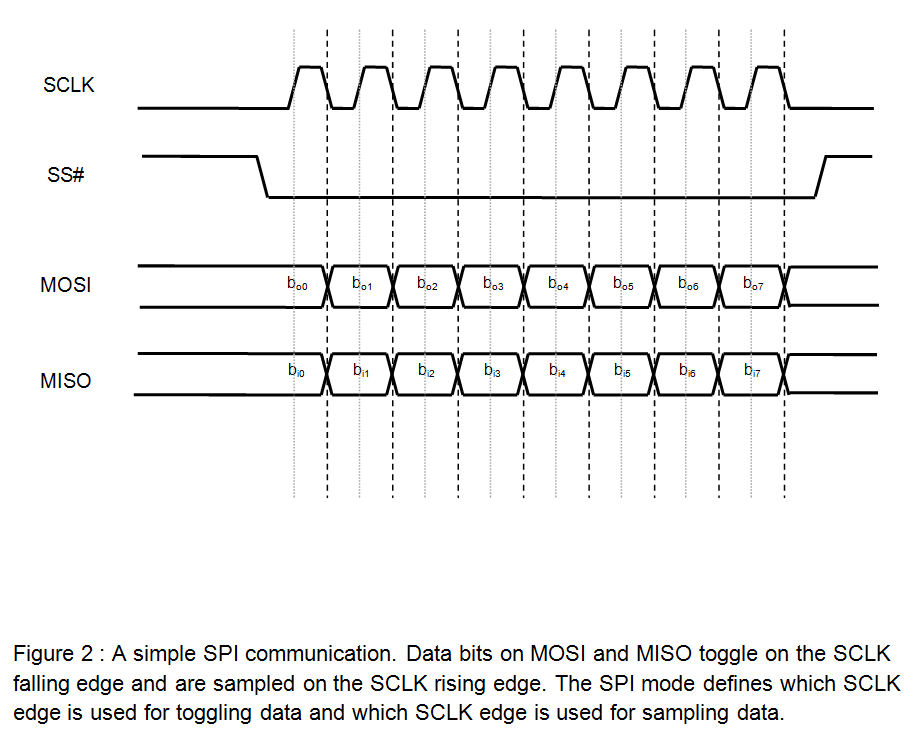
However, if you’re not reading the signals properly (even after you figure out that CS stuff), then you might be in the wrong “mode”. This relates to when signals are triggering. See here for more info:
Not sure if I answered this properly, but yes it should be “synced”. In reality, nothing should happen if CS is not low. This is because it’s a bus. You could have 5 different devices on the bus all listening to the MOSI line (master control coming from the Arduino, in your case). Only the device that has been selected–because each device would need to have a discrete CS–would actually be listening and then replying.
OK, first, remember that “there’s no such thing as an SPI standard!”
In general, since, as Chris points out, SPI is a “bus,” meaning that one can reasonably expect to hang more than one slave on it, yes, the MISO output of a slave should be tristated when that slave is not selected (its CS input is high).
Thank you @ChrisGammell and @Andy_P for the information. I did some more digging, as this problem is quite perplexing.
According to the W5500 Datasheet, when pin 32 (SCSn) is pulled low, pin 34 (MISO) starts spewing SPI data.
Simple. right? In theory, I should be able to pull that pin low using any Arduino pin set as an output and be off to the races. So, I did this (soldered W5500 SCSn to a trace, verified that my jumper was functional by using it with pin 10), tried using it with another Arduino pin set to an output and pulled low, but it still didn’t work.
But why? In my original post, I had mentioned that the CS pin on the Arduino (10) looked funny on the scope. I did some further investigation, and it looks like this:
If I put my scope on another Arduino pin set as a low output, I get a nice flat line at 0V. If I do the same but set the output high, I get a nice flat line at 5V.
To add to the mystery, this is what the SPI decode looks like using Arduino pin 10 for the SCSn (W5500 works):
The W5500 only works when using Arduino pin 10 as the SCSn (CS) pin.
Any other Arduino pin pulled low causes MISO to not function properly (?)
It looks like some library somewhere is strobing pin 10 at 58kHz. But why?
I am going to take a look at the W5500 source to see if I can find anything interesting, but until then, as @Andy_P said, there is no such thing as a SPI standard, right? Any ideas what may be going on here?
You should dig into the Arduino documentation and make sure that the pin you think is the chip select (CS) is actually being driven out as the chip select, and its pin configuration is correct.
Edit to add: I opened up the Arduino environment, selected the Mega, and loaded the Digital Pot Control example. The comments in the code indicate that the chip select output is routed to Digital Pin 10.
Okay, took a look at the W5500 code and noticed that in utilities/w5500.cpp that in the read/write operations, there are two functions being called before and after RW operations, respectively: setSS() and resetSS(). Interesting.
For reference, all of the Arduino pin settings may be found in their Github.
Reading the documentation, it looks as if the W5500 can operate in either Fixed Length Data Mode or Variable Length Data Mode.
If SPI Operation Mode is set as Variable Length Data Mode (VDM), SPI Bus Signal SCSn
must be controlled by the External Host with SPI Frame step.
At the Variable Length Data Mode, SCSn Control Start (Assert (High-to-Low)) informs
W5500 of SPI Frame Start (Address Phase), and SCSn Control End (De-assert (Low-toHigh)
informs W5500 of SPI Frame End (Data Phase End of random N byte).
Well, there you have it. The chip select pin is used to frame SPI comms.
Documentation folks, it’s there for a reason.
Well, if nothing else, I learned quite a bit about SPI.
Thank you for all of the help! Hopefully this has been informative.


