Greetings all!
This is my Build Log. I am a self-taught electronics hobbyist. I hope to gain skills and knowledge as I progress through the course and beyond. Thank you @ChrisGammell for creating this awesome space!
Shine On
I followed along the tutorial and made a few small changes. I thought I’d use a mix of through hole and surface mount components of different sizes.
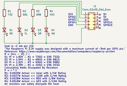
I took some LEDs I had and measured their forward voltage. My test conditions were VCC = 3V3 and the LEDs were in series with a 1K ohm resistor.

I then calculated the resistance values for a 2 mA current through the LEDs at 3V3. The 2 mA was decided on because according to the Raspberry Pi website, “The Raspberry Pi 3.3V supply was designed with a maximum current of ~3mA per GPIO pin.”
In my research about resistors, I learned about the E-series for resistors and other passives. I picked the E96 series even though 1% accuracy was a bit overkill, and rounded all the calculated resistances to the nearest E96 value. I was then able to complete my schematic.
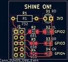
I paired up the 3mm red LED with a 1/4W through hole resistor, the yellow 1206 LED with a 1206 resistor, the orange 0803 LED with a 0803 resistor, and the green 0603 LED with a 0603 resistor.
I performed calculations to ensure that the power ratings of the resistors were acceptable for the current that was going to flow through them.
There’s a lot of new stuff in Kicad 7.0’s PCB editor, so I took some time playing around with it. The layout was pretty straightforward.
I ordered my PCBs from Oshpark and the remaining components from Digikey.
Soldering the board was pretty straightforward.
I had an old Raspberry Pi 2 laying around, and wrote a program in Python to blink the LEDs. It was my first time writing a program on the Pi that used the GPIO pins, so that was fun.

On to the next project!
Blinky… V1 - V5?!?
Alas, the trusty 555 timer, one of the world’s most well known ICs.
After doing some research and brainstorming, I had several different ideas for this project. Since I couldn’t decide on just one, I’ve decided to do them all.
Without further ado, here’s the first one.
Blinky V1: 555 Oscilloscope Playground
The objective of this variation was to create a board that I can hook up to my oscilloscope for examination of the 555 timer in astable mode. I wanted to be able to experiment with varying R1, R2, and C1. I also wanted to be able to change the power supply and be able to use the 555 timer’s output externally.
I was debating between potentiometers and fixed resistances. I ultimately decided upon fixed resistances as I could then do an experiment and compare predicted vs actual frequency and duty cycle. I decided that using DIP switches was the best way to switch between the resistances and capacitances. I chose E3 values between 1KΩ and 1MΩ for resistances and E3 values between 0.1μF and 100μF for capacitances.
I added two SPDT switches to the circuit, one for power and one for output. The power switch switches between a 3V lithium battery and off/external power. The output switches between an onboard LED and external output. Both the power input and output are fused and use a diode to protect against reverse polarity.
At first I had put a 1KΩ resistor in front of the LED. According to an article online, Red LEDs typically have a voltage drop of between 1.7V and 2.2V. Assuming a worst case Vf = 1.7V and allowing for 20 mA through the LED for a 18 V input voltage (the maximum allowed by the ICM7555) resulted in a resistor value of ~800Ω, so 1KΩ. A quick power calculation found that at that current the resistor would be required to dissipate > 0.3W, more than the 1206 1/4W resistor could handle. The next resistor I have, 2.2KΩ, would result in a current closer to 7.4 mA through the led at 18V. The resistor would be dissipating only ~0.125W, about 1/2 of the limit of the 1206 resistor. It just goes to show how important it is to calculate the power dissipated by components.
All resistors had 1% tolerance and all capacitors had 10% tolerance except for the 100µF electrolytic which had 20% tolerance.
The board layout was a bit more challenging due to the increased number of components. I added mounting holes so I could 3D print feet for it.
I ordered the board from JLCPCB and the components from Digikey. Soldering was pretty straightforward. I put together some feet in Fusion 360 and 3D printed them.
I used the following formulas to find the expected frequency and duty cycle values (resistor values in ohms and capacitor values in farads):
Time High in Seconds = 0.693 * (Resistor1 + Resistor2) * Capacitor
Time Low in Seconds = 0.693 * Resistor2 * Capacitor
Frequency in Hertz = 1.44 / ((Resistor1 + 2 * Resistor2) * Capacitor)
Duty Cycle in Percent = 100 * Time High / (Time High + Time Low)
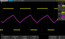
I picked an assortment of R1, R2, and C1 combinations. I calculated the expected frequencies and duty cycles, then used my oscilloscope to determine the actual values and frequencies for my board.
To determine percent difference, I used the following formula:
% Diff = 100 * Abs((Expected - Actual) / Expected)
For the combinations tested, the absolute difference between expected and actual ranged from 1% to 54% for frequencies and from 4% to 47% for duty cycles. Most differences were <10%. Conclusion: In the future if I used a 555 and needed accuracy, it would be best to check the actual frequency and duty cycle with my oscilloscope.

I found it quite interesting to see the correlation between voltage at the threshold/trigger (purple) and the output (yellow). It’s pretty cool to be able to see the capacitor charge and discharge!
I purchased an IoT relay so that I could toggle a 120V circuit safely. I thought why not try it with my 555 timer project. It actually works with the 3V lithium battery!

I’ll consider that a success… on to the next Blinky!
Blinky V2: MIC1555 / MIC1557
Ever find a couple quarters while cleaning your couch and wonder if you can get a gold plated PCB manufactured in exchange for them? Oshpark can do that for you! The blinky board for this project was only 40 cents.
For this project I wanted to make a very tiny blinky. After some searching, I stumbled across the IttyBitty® series of timers. There’s MIC1555 and MIC1557. Both come in a TSOT-23-5 package, which seemed hand solderable.
Being in a TSOT-23-5 package, they obviously lack the pinout of a standard 555 timer. Although the MIC1555 and MIC1557 have different abilities, both can be used as an astable oscillator.
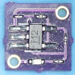
I ordered both and created breadboard friendly adapters for them.
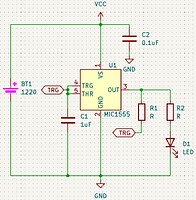
Both worked equally well in the “blinky” circuits found in the datasheet. I ultimately ended up picking the MIC1555 for my project because it required fewer external components.

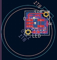
I picked an 0402 LED to blink because it was the smallest LED I could find that had pads on the side. For the resistors and capacitors I picked 0201 and 01005 components.
My biggest constraint was finding a battery holder for this project. I ended up finding a 1220 battery holder that would work, but it still made my board a bit bigger than it otherwise had to be. The minimum board size for Oshpark is 250 mils x 250 mils and mine is slightly bigger.
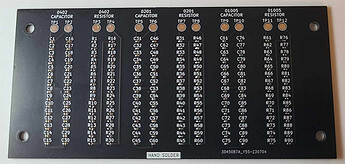
I made an 0402-0201-01005 practice board with the “HandSolder” footprints to prepare for this project. I had to find a grind stone for my tweezers to make them more even so they could handle the 01005 components. While soldering the board, I definitely learned the importance of flux! There’s some joints that could look better, but overall it was successful. For each of the component sizes, the capacitors in parallel had “infinite” resistance and the 30 1K resistors in series showed ~30K resistance, as expected.
After completing the practice board, soldering the Blinky V2 board wasn’t too bad. I’m actually pretty happy with how it turned out.
Finally, after soldering the battery holder and putting in a battery… it worked!

What challenges will Blinky V3 bring? Will I be able to solder it? Will I lose my mind in the process? Stay posted to find out!
Blinky V3: 1.41 x 1.44mm DSBGA 555 Timer
Never in my life have I hand soldered a BGA chip, so I figured why not start with an easy one. Haha. Texas Instruments produces a 555 timer in a GIGANTIC DSBGA (Die Size Ball Grid Array) package. For the small form factor at least it has full 555 timer functionality.
LMC555 Datasheet
Since I can’t see those pins for soldering, I figured why not try to solder an LED whose pins are underneath the package too.
This project has by far the most ambitious soldering I’ve ever done. Going into this project, I had no idea on whether or not I’d be able to successfully complete it.
I decided to use the same capacitor and resistor package sizes as V2. Being a full 555, it is the same schematic as the CE Blinky lesson, with a couple extra capacitors added for good measure.

The layout was pretty straightforward, but the footprint for the DSBGA looked daunting… and I after I ordered the PCB I saw I put the wrong footprint for the 0201 LED.

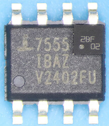
When the 555 arrived, I examined it under my microscope. Here it is compared to the SOIC 555 timer used in Blinky V1.
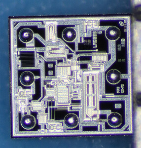
When I flipped it over, I couldn’t believe my eyes! It was the coolest thing I’ve come across so far in this hobby… the actual die of the 555! I wish there was a map of what etches did what. Here’s the best picture I could get of it:
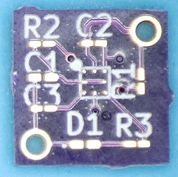
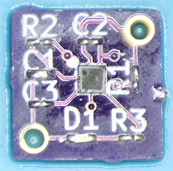
I decided to make a breadboard adapter for the 555 timer, and see if I could solder it properly.
I covered all 8 PCB pads with some solder, cleaned everything, added flux, lined up the package the best I could, added hot air, and crossed my fingers. I saw the chip shift slightly, I nudged it gently, and from what I could tell it was floating on the solder. I took away the heat and hoped for the best. When I set it up on the breadboard, somehow it worked!

Now the ultimate challenge. It was time to solder the V3 PCB.
The first time I tried soldering the board, I tried soldering the LED and the 555 timer at the same time. It was a disaster. Both the LED and the 555 timer flew with the wind of the hot air station. The worst part was that I lost the solder balls off the bottom of the timer. With no way to reapply them, I had to use another one.
The second time I did things more methodically. First, I put some solder on the pads for the LED, and using the hot air station, I managed to get the LED in position. I covered the LED with kapton tape, and applied solder to the PCB pads for the 555 timer. I soldered it the same way I had for the breadboard adapter. It seemed to be in position, so I soldered the rest of the components. I lost a few 01005 components into the nether… I’d like to imagine one day an ant will find one and bring it to their queen as a gift.
The moment of truth arrived when I finished soldering and put the battery in…

Woot! It worked! Let’s hope that V4 will work too!
Nice work on the BGA!! So many people are scared to even look at them.
