Kody's Build Log

I have been working on an 8 minute annoying buzzer along with going through Chris’s Current Sink or Swim class.

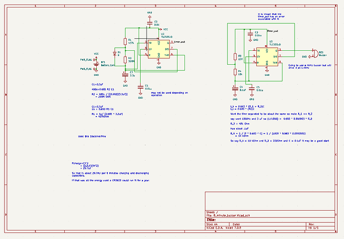
The 8 minute timer basically consists of one 555 timer that turns on another 555 timer for one second (roughly) every 8 minutes (roughly). The second timer buzzes a buzzer. It is meant to be like those annoying buzzing toys one could buy on amazon.

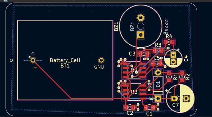
The 8 minute time arrived, but is not working correctly. It shows 0.65V at the discharge and output pins of the 555 timer that is supposed to delay the buzzing for 8 minutes. Below is a picture of the schematic and pcb layout. Everything else is also on GitHub here GitHub - PhysicsUofRAUI/disruptivetech: place to hold all docs wrt electronics meant to be annoying or disruptive.


Any ideas or suggestions on that problem would be much appreciated.

As for the current sink or swim it is going well, but I am taking some time to brush up on Op-Amps and transistors. I also am trying to do all the simulations with KiCAD.

After I complete the Current Sink or Swim I am going to finish the first board for a project which is meant to hoot at birds if they come too close to the device. That project info can be found here Hooter.

Sorry if this post seems a little scattershot. That’s just how I am sometimes :person_shrugging:

Dear Kody,
The annoying buzzer project sounds hilarious. I think it’s cool you’re working on multiple projects right now and hope you continue to post about them :slight_smile:
I’m just a hobbyist, so I hope someone with more knowledge responds to you, but I’ll give a go at trying to troubleshoot your circuit.
Here’s my questions so I can try and help more:

  1. Just out of curiosity, did you try to breadboard your circuit? If so, did have any issues with it when you did?
  2. Did you use a reference circuit or create it yourself? If you used a reference circuit, can you link to it?
  3. Can you give a list of the actual parts that you ordered or are using? (So I can see the parameters of the parts)

Here’s my best guesses:
I believe that the leakage current of your electrolytic capacitor is great enough to either cause C7 to charge very slowly, or worst case, not at all.
Let’s examine the circuit when it first starts up. Voltage across C7 is 0V. Vf of D1 could be approximately between 0.3-0.7V (depending on the type of diode you’re using), resulting in a voltage drop of 2.3-2.7V across R1.
I = V/R therefore ~5 to 6μA across R1 (437KΩ).
I’m not sure what electrolytic capacitor you’re using, so I pulled up a datasheet from Panasonic. Panasonic Aluminum Electrolytic Capacitors Datasheet It says the leakage current is “I ≦ 0.01 CV or 3 (μA) After 2 minutes (Whichever is greater)”. I’ve seen some graphs that suggest the leakage current is even greater initially. Here’s an example.That means a significant amount of the initial charging current for the capacitor could be leaking through it, seriously affecting the ability of C7 to charge, and therefore affecting your timing.
Also, R2 has a value of ~200MΩ. Doing the same math, the leakage current of the capacitor is much greater than the current that is able to go through that resistor at that voltage. The threshold and trigger pins have a current too, but it seems as if it is a few orders of magnitude lower than that leakage current.

I also think that it is possible that your 555 might not be able to source enough current to power the other 555 timer and the buzzer. I read that a generic buzzer can use ~10mA although I don’t have one to currently test. If you take the datasheet of the 555 timer I used in the project, according to Figure 9, I don’t think it would be able to power the second 555 timer and its buzzer at 3V. If you compare Figure 9 and Figure 10, it seems as if there can be a difference as to how much current the output pin can source versus how much it can sink.
Please take what I said with a grain of salt, as I realize that it is likely that I’m wrong.

Guidelines I’ve found:

  1. According to multiple sources I’ve seen, it’s best to try and use resistor values of between 1K and 1M. “For standard 555 timers use timing resistor values between 1K ohms and 1M ohms.” 555 Timer Tutorial - Resistor Values
  2. According to multiple sources I’ve seen, electrolytic capacitors shouldn’t be used for the 555 timing circuit because of their variability (up to 20% or more) and because of their leakage current. 555 Timer Tutorial - Capacitor Leakage Here is a cool article I found on the leakage current of capacitors depending on type and other parameters: Leakage Current Characteristics Of Capacitors.

Here’s what I’d do if I were you:

  1. I’d breadboard the left part of the schematic, and for output I’d use an LED in series with a 1K resistor and power it with the 3V battery. Does the LED flash with the current components? I’d likely hook up an analog Arduino pin to monitor the output( eg. U3 Output to Arduino A1 and Breadboard GND to Arduino GND) and write a program to display the voltage over time in a graph over the serial monitor (or a program that lets me know when the output reached a threshold voltage and for how long). If it didn’t work, I’d decrease R1 and R2, and increase C7 according to the guidelines on this link or the 555 timer’s datasheet. Also for C7 I’d try using several ceramic or film capacitors in parallel to get the capacitance for the desired timing. You might be able to get away with higher than 1M resistors if you use capacitors with lower leakage currents?
  2. Once I got the left side of the schematic working, I’d breadboard the right side. Instead of hooking it up to timer_out, I’d hook it up to 3V to make sure it worked with the buzzer. If it didn’t work, I’d try powering the buzzer through U2’s output using a transistor or mosfet. Alternatively, I’d try sinking the buzzer with U2’s output instead of sourcing it. If that didn’t work I’d try powering the circuit using a source with a higher voltage (eg. 5V) and capable of sourcing more current (eg. USB power supply) to see if it worked then.
  3. With both the left and right side of the schematic working, I’d hook them up like in your schematic. If it didn’t work, I’d try powering U2 through U3’s output using a transistor or mosfet. If that didn’t work, I’d probably power the circuit using a source with a higher voltage (eg. 5V) and capable of sourcing more current (eg. USB power supply) and see if that worked.

I hope it was what you were looking for and that you found it helpful. Please let me know how your troubleshooting works out.

Regarding your hooting owl circuit, I suggest you look into low power modes for the AVR microcontrollers. Nick Gammon made an amazing post on low power states of microcontrollers. Arduino docs has a great article too.I agree with your posts about having the ATMEGA328P wake up periodically, power the sensor via a mosfet, take a reading, turn off the sensor, then go back to sleep. There are some ultrasonic sensors that work at lower voltages. This one goes down to 3V. If you can get the PCM library to work with the ATMEGA328P running at 8 MHz, then you would probably be able to run the project off 3 AA batteries in series. They’d start off at ~4.5 V and be good until they got down to ~3 V. If you were able to put the ATMEGA328P into sleep mode, waking it up every 8S with the watchdog timer and taking 0.5S to operate the sensor, then you’d be averaging about (8 S * 0.005 mA + 0.5 S * (4 mA Sensor + 4mA ATMega)) / 8.5 S or 475µA instead of the 4 mA you’ve calculated for the sensor alone. The 4 mA sensor value was from your post and the 4mA ATMega was from this datasheet. Assuming 2000 mAh like you did, that’s 2000mAh / 0.475 mA, or ~ 175 days. If you were able to sleep for longer or decrease the on time of the sensor, I totally think it is feasible to power your project for a year off of batteries. I would suggest using the lithium AA batteries because in my experience they can handle -40C a lot better than the alkaline ones.

Sorry for the long reply. I can remove it if it is in the way of your build log.
Take care,
-Murray

Thanks for the great reply (it is by no means too long, I love hearing others thoughts). I am also just a hobbyist at the moment too.

I’ll start with that I solved my 555 buzzer and long timer circuit. Embarrassingly enough the problem was the [expletive] ground. I was sure I double checked all the solders, but when I got the circuit working on the breadboard I rechecked them and sure enough the ground of the long timer was not connected.

Your points about using a larger capacitor are interesting though and I may do that. As to your request about the actual parts the timer is TLC555, and the rest I’ll add to my GitHub soon.

I’m definitely going to read up on capacitor leakage current, and all your great inputs for my hooting owl project.

Thanks again for your reply.

This will be a short build log, because I am a wee bit tired.

I have things to report on three different projects

  1. The Owl Hooting Project.
  • I have received a couple of louder speakers from digikey and I tested the loudest out. It appears to work well (now that I have it working correctly). More info can be found here Hooter Louder Speaker, and a demo can be seen on YouTube https://www.youtube.com/shorts/UxonB4UgZeo.
  • I have also created a base wiring schematic using the ATMEGA328, but after reading Murray’s reply more carefully I realize I need to make some changes to the circuit to turn on and off the ultrasonic sensor (I didn’t include the Mosfet :face_with_open_eyes_and_hand_over_mouth:).
  • main problem with this project is the power still and will be working on it while field testing. Will definitely be looking closely at Murray’s advice again!
  1. The buzzer circuit
  • I ordered a batch mostly assembled from JLCPCB and those aren’t working now!
  • I assembled and tested 5 of them and none of them work. I had the thought it may be because some of the components aren’t designed to operate at 3V so I wired a 9V battery to one and got some action, but not quite right still (more of a weird buffering sound).
  • Right now the plan is to test it at 5V and if it works desolder the timers on one of them and put the timers that I know work on to see if JLCPCB put the wrong timers on (I did check to make sure the ones I ordered operated at 3V).
  1. Current Sink or Swim and OpAmps
  • I finished all of Chris’ videos up to the assembly of the CSOS, but have not yet ordered it yet. I just did not feel like I understood it enough yet.
  • I decided to learn more about OpAmps and while furthering that goal I have simulated many of the classic OpAmp circuits and stored them in a GitHub repo.
  • Now I plan to set up those classic circuits on the bench and go back to the CSOS project and add in some test points so it is easier to test than the original version.

Well I think that is all. I welcome all comments and suggestions.