Well done. I like it. I could use one immediately, although I’d use one channel for pump control. Looking forward to hearing of your test results.
What have you selected for front panel buttons? I’m looking at a series from one of my wholesalers “LAY5 Industrial Power Switches”, often seen in crane control boxes.
I did some PWM tests and that looks great (will post some scope shots when I have time). For pump control I would use a relay or SSR. There are a couple of PCB mount SSRs that don’t break the bank ($10-$15 range), but it depends on how beefy your pump is.
I haven’t fully decided on buttons yet. I live in the dry part of california so waterproofing is relative. I bought some cheap membrane buttons and want to experiment with those, they’re similar to
and I want to glue them to the top of the clear cover and either put some clear tape over them or some conformal coating around the perimeter. I haven’t examined them under the microscope. Plan B is to get some “waterproof” buttons with through mount, but these are either expensive or the “waterproof” needs to remain in quotes…
I should say that I do all the irrigation programming and reporting over MQTTS to the esp32 so the display and buttons are only there for maintenance, e.g., turning a valve on to check that all the sprinklers are working and stuff like that.
Since I posted the schematic I should write some (random) design notes:
I opted for 12 valves 'cause that fit the esp32 pin count without pushing to the limit, it would be possible to go to 16 with compromises
the design is for two valves to be active simultaneously allowing for a master valve and 11 branch valves
valves are expected to consume < 1A under DC drive, traces and some components would need beefing up for higher currents
there is a 1Ohm current sense resistor, I’m using a 1/4W SMD, which should be OK, but I added through holes for a 1W part just in case
the display is minimal and, together with the buttons, is intended for troubleshooting, e.g. to manually turn a valve on to check sprinkler operation. The irrigation schedule programming is intended to happen over the network
the usb connector is for programming/debugging purposes, I included the cp2104 because it ended up being cheap and I had never done that before, normally I use just an FTDI serial interface and my PCB has holes for a 1.27mm FTDI connector in case I botched the CP2104 hook-up
The “meter” connector is for a hall-effect flow meter
The esp32’s IO4 pin is unused and there’s a through hole for a connector in case it’s needed
The connectors are designed for 5-conductor direct burial low voltage 18ga cables (which are common at home improvement stores around here): one conductor carries 12V the other four drive GND to each of four valves. Hence 3 connectors for 3 cables for 4 valves each.
I recommend that you have isolation from the AC line. You don’t want ground faults.
I had a small COTS timer running my sprinklers and there was a lightning strike nearby. All those control wires had induced voltages high enough to toast the controller.
I would have considered drivers based on current rather than voltage as there could be long cable runs and poor connections.
@iabarry thanks for the comments! The input to the board is 12VDC, the isolation from A/C is done in the wall wart or equiv. Maybe that’s what you mean?
Interesting comment about lightning. Fortunately lightning is very rare hereabouts. But what should I have done? Add an 18V 20A MOV across each valve? Something like https://www.bourns.com/docs/Product-Datasheets/MLA.pdf ? I could retrofit that manually…
I’m not sure how current drivers would work. The PWM drive works real well and reduces the power consumption of the solenoids (and thus their heating) significantly, and the current consumed by the various valve types varies quite a bit.
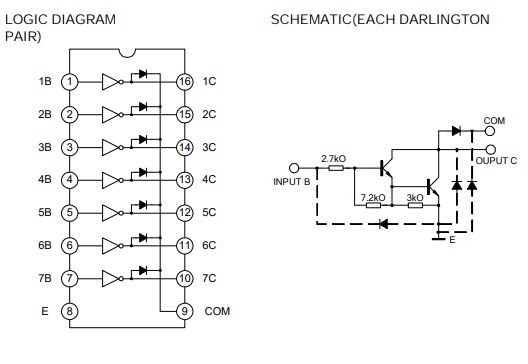
You could reduce the component count of this project by 90% if you could use the ULN2803 type ICs. They contain an array (normally 8 identical circuits) made to drive inductive loads like relais. It contains the pull down / free wheel diode and darlington output. At a one of price of $0.15 for an IC with 8 drivers on board you can not beat this with a discrete solution.
If you have 2 valves open for a total of 2A then you have reduced Vgs voltage on the FETs due to the 1 ohm source sense resistor. Only 1. 3V left for the FET and it won’t turn on fully
Interesting! Thanks for the pointer! I had looked for FET arrays but not darlington NPN. The chip you mention doesn’t have the drive strength needed in this application (more than 500mA) but a quad version like the ULN2066B does. I wasn’t aware of this ULN series, good to know .
Looking at efficiency, the quad NPN chips don’t come in small SMD packages, so they end up using just about the same board space as discrete FETs + diodes + pull-down. In terms of cost, the jlcpcb jelly bean parts and automated assembly are hard/impossible to beat. But if I had to hand-assemble I would gladly pay extra to solder a 16 pin DIP over all the discrete parts.
Yup, you are totally correct. That’s one of the areas where I don’t know what the outcome will be. I had a 1 Ohm assembled by JLCPCB but put a footprint for a large discrete resistor right next to it in parallel. I could populate that easily with another 1 Ohm to cut the drop in half or even a std jumper to be able to select.
The expected mode of operation is to drive a valve at 100% duty cycle for 200-300ms and then switch to PWM at 30%-50% duty cycle. The highest current is during the initial 100% and I’d like to accommodate as high as 1A, although the valves I tested draw < 600mA. Thereafter, during the PWM on-time the current is less than half of that. I’m planning to avoid turning two valves on at the same time in the software, and I’m pretty sure I can set-up the PWM so they are phase shifted as well.
The thought that made me keep the 1 Ohm resistor is that it provides a bit of short-circuit protection by turning the FET off if the current becomes excessive. What I don’t know is whether the circuit can sit in a half-on state that kills the FET due to excessive heat. Then it may have been better to “let the current though” and rely on the poly fuse?
Limiting the current with a 1R resistor is not a good idea as it likely will overheat the mosfet as the Vgs drops to low. It can work but than you must lower the sense resistor and sample the voltage over this resistor or use a comparator in order to take action when an overcurrent occurs. Without taking action it will likely overheat the mosfet. At 0R25 the voltage drop is 0.5V at 2A which might work. I like your idea of relying on the poly fuse. In that case you might as well do away with the resistor completely. This also simplifies your circuit.
If you want to make the unit more flexible I would measure the DC supply voltage with the ESP32. This way you can adapt your PWM according to the supply voltage. Say you got 12V coils but your supply measures say 24V. You basically adapt the PWM output in order to get a 12V output. This makes the unit also more proof to supply fluctuations as well. Also can you use the unit as a 24V system.
So I tested the over-current situation. Interesting…
I put a 1Ohm resistor instead of a valve and generated a 40ms ON pulse. The sense resistor showed the current jumping to ~1.8A and then slowly increasing. I extended the ON period to 80ms and the MOSFET blew up.
What’s interesting and concerning is that the esp32 got damaged. At the moment it exits the bootloader and starts the app it generates a brownout reset and I can’t reprogram the thing. I checked the power supply and there’s no drop to see at all.
When the MOSFET failed it shorted out and I suspect that this included the base with the result that 12V went into the esp32’s output pin. Ouch. So I’m clearly missing a series protection resistor or diode.
Interesting. I’d go for a reverse diode from gate to logic supply, and some series gate resistor. But larger gate resistance means having to be careful with PWM so that the MOSFET does not spend too long in that unpleasant region of gate voltages.
Looking at your schematic, what’s R15 on Q1 between gate and source there for? I guess to cover for I/O pins configured as input during reset?
Yes, the pull-downs on the FET gates are there to turn the FETs off when the uC output pin is not driven, e.g. during reset.
I’m thinking to reduce the sense resistor’s value a bit and put some form of detector on it that turns a high-side switch off, thereby cutting power to all the outputs.
Hi Ray thank you for your detailed information.
I had issue with my sprikler actually I’m controlling Hunter(24VAC) valves using with 5V relay connected by port expander(PCF8574) with ESP8266 and 24VAC is taken from step down transformer(220V/24VAC 2A) and also pump (1hp 5.8A) controlled by the same controller (ESP8266) Now the problem is suddenly sometimes(very frequent) all relays are turning-off automatically it’s not software issue (ensured by connecting valves to gpio directly working) issue is only with port expander and valves how to resolve this issue please give some ideas to overcome this issue
Could it be that you have a glitch in vcc that is triggering the power on reset of the expander?, this is from the PCF8574 data sheet:
10.1 Power-On Reset Requirements
In the event of a glitch or datacorruption, the PCF8574 device can be reset to its default conditions by using the power-on reset feature. Power-on reset requires that the device go through a power cycle to be completely reset.This reset also happens when the device is powered on for the first time in an application
Great work, @tve ! I’m surprised that it is so hard to find anything on the Internet regarding controlling 24V AC sprinkler valves by DC and PWM.
Now I’m planning my own sprinkler system. With my home automation system I have 24V DC power supplies and don’t like to add another big AC power supply just to control 6 or 8 valves / solenoids. With the home automation system I have a DMX bus that is commonly used to control / dim lights. There are cheap 12-24V DC DMX dimmers available from China, e.g. Aliexpress that have MOSFETs as drivers and they all use PWM to dim the outputs.
Inspired by your post I did some tests with a DMX controller called WS-DMX-6CH-BAN (6 outputs), 24 DC power supply, a Hunter 24V AC solenoid for PGV sprinkler valves and - it works! Initially I killed one of the MOSFETs before I remembered that flyback diodes are strongly recommended when controlling solenoids with MOSFETs. With these in place, I was able to reduce the duty cyle to 40% to open the valve and 20% to hold it open (with 24V DC!). I was able to measure power consumption with a multimeter and it was 3,4W to open and 0,6W to hold the valve open. I don’t have an oscilloscope to measure pwm frequency, however. The solenoid stayed cool for over an hour.
My question to you: how does your controller work over a long period until now?