My hobby these days seems to be revisiting concepts and topics I was once comfortable with and re-investigating them…! Today’s topic is the humble inductor; There seems to be a lot of sources around the place that can’t quite agree on why an inductor behaves the way it does.
Off the top, the mathematical models are ok; the inductor equation, solving the differential equations and comparing them to experimental results is not a problem; and so i have no issues with what an inductor does and how to use it, but how and why it is the way it is.
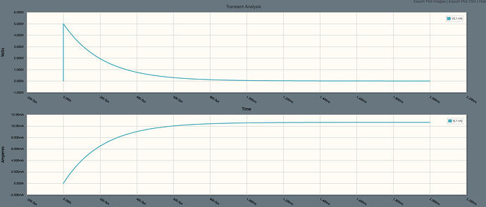
consider the step response to an RL circuit;

- at t<0, there is no voltage, and no current
- at t=0, the voltage steps up to (as an example) 5v and current will begin to flow
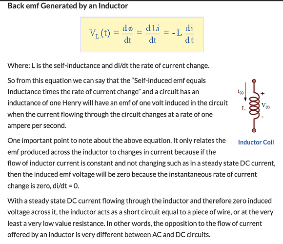
- as current has gone from 0 to over there is a rate of change in current, di/dt
- the changing current will, in the inductor (we will ignore parasitic inductance for now), creates a changing magnetic-flux which is proportional to the changing current.
- As Faraday showed, a changing magnetic flux induces a proportional EMF. Lenz showed that the polarity of the induced EMF will be opposite to the source that created it.
Now, the most common explanation I read is something like this “as the current through the inductor can not change instantaneously (as an instant change requires the time taken to make the change to be 0; so an instant current change would require di to be some value, but dt would be 0, making an infinite self induced voltage) and this can’t happen. Thus immediately after switch on, there is some voltage across the circuit, but 0 current. From a black-box perspective, the inductor would look like an open circuit; and so the source voltage would appear across the inductor Current will then start to rise, i.e.: there is now a di/dt; as there is increasing current, there is an increase in flux generated in the inductors windings. An increasing flux generates a voltage that opposes the source voltage and acts to limit the rate of change of current in the circuit. If the rate of change of current in the circuit reduces, the rate of change of flux in the inductor reduces and so the induced emf in the inductor also reduces; with less induced EMF, more current can flow, and the cycle repeats. After some point the voltage across the inductor will be 0, and so, from a black box perspective, it will look like a short circuit, the source voltage will now be across the resistor and the current will be as per ohms law V/R. We now have a steady state”
if we now suddenly remove the voltage source, the magnetic field rapidly collapses, which is a huge rate of change of flux, which in turn causes a large induced emf proportional to the rate of change of flux; The current created by the induced voltage has to go somewhere and it can have very nasty consequences. If the current meets something low resistance, say a FET, it will have a high current; if it meets something high resistance (say, the air gap of a switch), the voltage will appear across that gap, generating a low current, but a high voltage enough to cause a spark (then I assume there will likely be some small current feeding back into the power source as well!) → the solution here is a free-wheeling/flyback/snubber diode across the inductor
we can easily show the above experimentally, and we can solve it mathematically.
the voltage across and current through the inductor from the circuit above (this result makes mathematical and experimental sense to me)
We can apply the fly-wheel analogy and we can also say things like “the inductor will try and maintain a constant current” - conceptually this is fine, and is an easy way to quickly explain something, but in thinking about this topic more, I tend to dislike these analogies more and more - they are useful to a degree, but in the long term (at least for me) they tend to create more questions than answers
as we established, the induced emf in the inductor is a result of the changing flux which itself is a result of the changing current. So, what sets the “initial” rate of change of current (di/dt) which will set the initial induced inductor emf? I have read (and i can’t find the source just now, but will update this post when i find it) that the induced emf will be equal to the source voltage initially. Given the circuit above, if the inductor is acting as an open circuit then it must have the source voltage across is (though, if we pretend we don’t have V = L di/dt, then I am yet to make a good mental model of why this is). But on the other hand, I can’t see anything in the physics that says this must be so - if you had a sufficient size inductor and/or sufficiently high di/dt, then L di/dt could in theory be higher than Vs. If L and/or di/dt was low enough then Vl could also be lower than Vs. This is described here (https://www.allaboutcircuits.com/textbook/direct-current/chpt-15/inductors-and-calculus/#:~:text=The%20instantaneous%20voltage%20drop%20across,L%20(di%2Fdt).) in that a potentiometer is used to control the current in the circuit - so i imagine this as if you started with the pot as an open-circuit, then slowly wound it from higher-resistance to lower-resistance, you could then control di/dt; if you wound at a constant speed, the gradient of the graph of Current vs Time would be constant and you would expect the induced EMF in the inductor to be L * di/dt which would be some constant - if you wound the pot slow enough the induced EMF could be quite low… eventually you would stop winding the pot; di/dt = 0, and so the induced emf = 0; the inductor now has some constant magnetic field as long as the current remains constant. ← this makes sense!
if we take the step response, you have a near instant voltage change - if it was ideal, then the dv/dt would be infinite - lets be grateful then that it’s not ideal and the voltage takes some time to ramp up. I guess the voltage ramp-up time is some complex function of the PDN inductance, capacitance, resistance as well as the power supply itself, internal resistance/inductance/capacitance etc. But lets assume that it’s a pretty sharp rise - if the circuit was purely resistive, di/dt would be proportional to dv/dt - they would have the same slope. In my example circuit above, a di/dt of at least 50 A / second would lead to a V(inductor) of 5v; anything higher than 50A/s would exceed the 5v source… but if there is 5v of induced voltage across the inductor - that would negate the source voltage and no current would flow; the magnetic field created by the short burst of initial current would collapse, probably generating a short pulse of high voltage… and the process would start again, assuming nothing released the magic smoke, there would be a constant tug of war; clearly this is not what happens - so my guess here is something limits the initial current change to something much less so the induced voltage is low enough to oppose the current flow, but not stop it entirely… (because we know mathematically and practically how these circuits operate - so I have clearly missed something)
I think I will stop here, as moving on might build incorrectly on a misconception - though I am looking at how we then get from t=0 to steady state as it’s not quite adding up right now!
as I say, I know I am wrong somewhere, I can prove mathematically that I am wrong! but I don’t see where right now …


