Hi!
many moons ago I posted this topic: Current Flow in an (AC) RC Circuit (Low Pass Filter). And I wanted to get back to it, however reading that topic now, it went off on a tangent. So, forking a discussion to hopefully keep things in line.
This is a classic, 7805 circuit, and will serve as a useful reference - but first, would the proper term for C1 and C2 be “decoupling”, “bypass”, “filter” or “smoothing” capacitors - I have seen all used interchangeably, and to some degree all seem correct.
in any case, no matter what they are called they serve two main purposes
- filter any noise away from the Vcc line
- provide a reservoir of power for a short burst incase the 7805 pulls a higher amount of current
→ essentially ensure the Vcc line is a smooth, and stable as possible
we all know this; but given Muntizing in a thing, and given this video from Dave Jones recently (https://www.youtube.com/watch?v=PgHQ7ES1uDk)
maybe I’m not the only one who needs a refresher on how bypassing works (and how to do it properly!)
as I see it, there are some issues - and after simulating, thinking, reading and researching, I believe I have found the source of my error, and that is that I have been assuming ideal components. If we assume ideal capacitors and voltage sources, then I think there is a paradox here - that is my hypothesis, but I would love feedback.
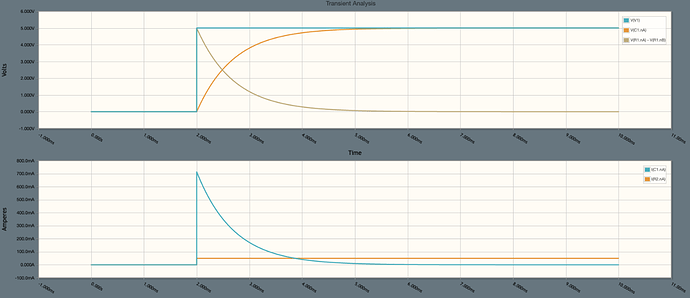
Referring to the 7805 circuit above (though the 7805 could be any device of course, an MCU being another good example). If we assume at t<0, the capacitor is discharged, when we add power, what will be the voltage at node A? Vcc is attempting to make it 5v; however at the same time, there is 0v across the capacitor. And this seems to be a paradox! However the capacitor is not ideal, there is resistance and inductance as well. If i add a series resistor in (a simplified model) then the simulation appears as I would expect.

- the voltage across the capacitor rises as expected to Vcc
- the voltage across R1 (in series with the capacitor) decreases to 0 as expected
- the current through the load R/C branch decreases as expected (as the voltage across the capacitor ramps up to Vcc)
- the current through the load is Vcc/RLoad
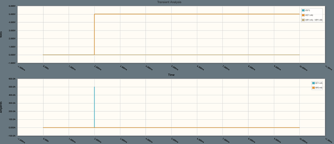
if i remove the parasitic resistance (set it to 0) - then we get maybe what I expect - and that is a spike of 500A through the capacitor, and Vi across the load… in this case perhaps the simulation resolution is not good enough to see the detail. But in the real world, I can imagine this would be a problem

at this stage, i will pause and ask am I correct?
- is the ESR of the capacitor preventing the problem i describe?
- have I misunderstood somewhere, and in fact there isn’t an issue in the first place? (i.e.: an ideal capacitor would function just fine)?
thanks! If i am correct, then I have follow up questions/theories!


